Proform PFEL05807 User Manual
Browse online or download User Manual for Sports and recreation Proform PFEL05807. ProForm PFEL05807 User Manual
- Page / 28
- Table of contents
- BOOKMARKS
Summary of Contents
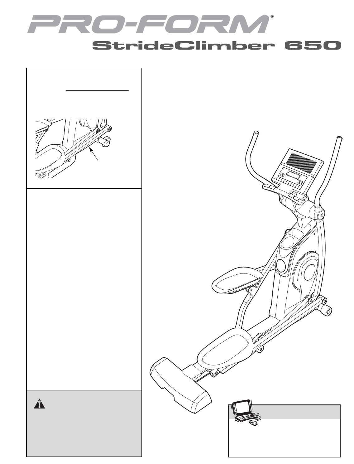
Serial Number Decal (under frame)CAUTIONRead all precautions and instruc-tions in this manual before usingthis equipment. Keep this manualfor future r
1011. Orient an Inner Handlebar Cover (18) and anOuter Handlebar Cover (19) around the RightHandlebar (9) as shown.Attach the Outer Handlebar Cover (1
1113. The Console (5) can be operated with four 1.5V“D” batteries (not included); alkaline batteriesare recommended. IMPORTANT: If the ellipti-cal exe
1216. Make sure that all parts of the elliptical exerciser are properly tightened. Note: Some hardware may beleft over after assembly is completed. To
13HOW TO USE THE ELLIPTICAL EXERCISERHOW TO MOVE THE ELLIPTICAL EXERCISERDue to the size and weight of the elliptical exercis-er, moving it requires t
14HOW TO ADJUST THE SELECTORThe pedals on the elliptical exerciser move your feet ina natural elliptical path. You can adjust the selectorson the elli
15FEATURES OF THE CONSOLEThe advanced console offers an array of featuresdesigned to make your workouts more effective andenjoyable.When you use the m
16HOW TO USE THE MANUAL MODENote: If there is a sheet of clear plastic on the face ofthe console, remove the plastic.1. Begin pedaling to turn on the
175. Measure your heart rate if desired.If there are sheets ofclear plastic on themetal contacts on thehandgrip pulse sen-sor, remove the plas-tic. To
18HOW TO USE A WEIGHT LOSS WORKOUT1. Begin pedaling to turn on the console.See step 1 on page 16.2. Select a weight loss workout.To select one of the
19HOW TO USE A PRESET WORKOUT1. Begin pedaling to turn on the console.See step 1 on page 16.2. Select a preset workout.To select one of the eight pres
TABLE OF CONTENTSWARNING DECAL PLACEMENT . . . . . . . . . . . . . . . . . . . . . . . . . . . . . . . . . . . . . . . . . . . . . . . . . . . . . .
Inspect and tighten all parts of the elliptical exerciserregularly. Replace any worn parts immediately. To clean the elliptical exerciser, use a damp
21These guidelines will help you to plan your exerciseprogram. For detailed exercise information, obtain areputable book or consult your physician. Re
22SUGGESTED STRETCHESThe correct form for several basic stretches is shown at the right.Move slowly as you stretch—never bounce.1. Toe Touch StretchSt
25EXPLODED DRAWING A—Model No. PFEL05807.1 R0108A89719684818018194179934181011878888141333339337289333334141428285712222434354182828383933054608283313
231 1 Base2 1 Frame3 2 Outer Crank Arm Cover4 2 Inner Crank Arm Cover5 1 Console6 1 Upright7 2 Roller Cover8 1 Left Handlebar9 1 Right Handlebar10 2 H
2481 2 M10 x 20mm x 2mm Washer82 14 M10 x 15mm Patch Screw83 14 M10 x 25mm x 1.5mm Washer84 2 M4 x 16mm Flange Screw85 8 M4 x 12mm Screw86 6 M4 x 16mm
262348647368675156651712679747466395959517777786868636753844454743299475739363875707036674744047529696945820475361735059796256446320858569252597787276
271118193333417979808193153131303233335460721222435414141414282838382828282828288838388879102984719641939386797979791685933498494689838383EXPLODED DRA
Part No. 262879 R0108A Printed in China © 2008 ICON IP, Inc.ORDERING REPLACEMENT PARTSTo order replacement parts, please see the front cover of this m
3WARNING: To reduce the risk of serious injury, read all important precautions andinstructions in this manual and all warnings on your elliptical exer
4BEFORE YOU BEGINThank you for selecting the revolutionary PROFORM®STRIDECLIMBER 650 elliptical exerciser. The PROFORM STRIDECLIMBER 650 elliptical ex
5ASSEMBLYTo hire an authorized service technician to assemble the elliptical exerciser, call 1-800-445-2480.Assembly requires two persons. Place all p
61.While a second person tips the Frame (2) backward, attach a Wheel (25) to each side ofthe Frame with an M10 x 35mm Shoulder PatchScrew (94).2. Care
73. Identify the Right Roller Leg (21) and the RightPedal Leg (16), which are marked with “R”stickers. Orient the Right Roller Leg and theRight Pedal
86. Attach the Center Frame Cover (27) to the Base(1) with six M4 x 12mm Flange Screws (73).62717373735. Apply a small amount of grease to the axle on
98. Have a second person hold the Upright (6) nearthe Frame (2) as shown.Pull the Wire Harness (48) out of the Frame (2)and insert it upward through t
Related products and manuals for Sports and recreation Proform PFEL05807
 (30 pages)
© 2020, manymanuals.com. All rights reserved. | 1.406 s |
 Manymanuals.com
 Manymanuals.de
 Manymanuals.fr
 Manymanuals.it
 Manymanuals.pl
 Manymanuals.cz
 Manymanuals.es
 Manymanuals-pt.com
Comments to this Manuals