ProForm HGBE8991.1 User Manual
Browse online or download User Manual for Fitness, gymnastics & weight training ProForm HGBE8991.1. USER`S MANUAL
- Page / 16
- Table of contents
- BOOKMARKS
Summary of Contents
QUESTIONS?As a manufacturer, we are com-mitted to providing completecustomer satisfaction. If youhave questions, or if a part isdamaged or missing, PL
10STORING THE WEIGHT BENCHTo store the weight bench, place the Wheels (13) inthe base bracket on the weight rack included with theHIDDEN GROVE furnitu
11EXERCISE GUIDELINESTHE FOUR BASIC TYPES OF WORKOUTSMuscle BuildingTo increase the size and strength of your muscles,push them close to their maximum
12• Rest for one minute after each set for a toning work-out.•Rest for 30 seconds after each set for a weight lossworkout. Plan to spend the first cou
13MONDAYDate:/ /EXERCISE WEIGHT SETS REPSEXERCISE WEIGHT SETS REPSEXERCISE WEIGHT SETS REPSAEROBIC EXERCISEAEROBIC EXERCISETUESDAYDate:/ /WEDNESDAYDat
14Note: “#” indicates a non-illustrated part. Specifications are subject to change without notice. See the back coverof this manual for information ab
12345667899101010101111121221212114202016171816182020202020191313222223232323231515EXPLODED DRAWING—Model No. HGBE8991.1 R0305A
To order replacement parts, see the front cover of this manual. To help us assist you, please be prepared to givethe following information when callin
2WARNING DECAL PLACEMENT . . . . . . . . . . . . . . . . . . . . . . . . . . . . . . . . . . . . . . . . . . . . . . . . . . . . . . . . . . . . . 2I
31. Read all instructions in this manual and allwarnings on the weight bench before usingthe weight bench. Use the weight bench onlyas described in th
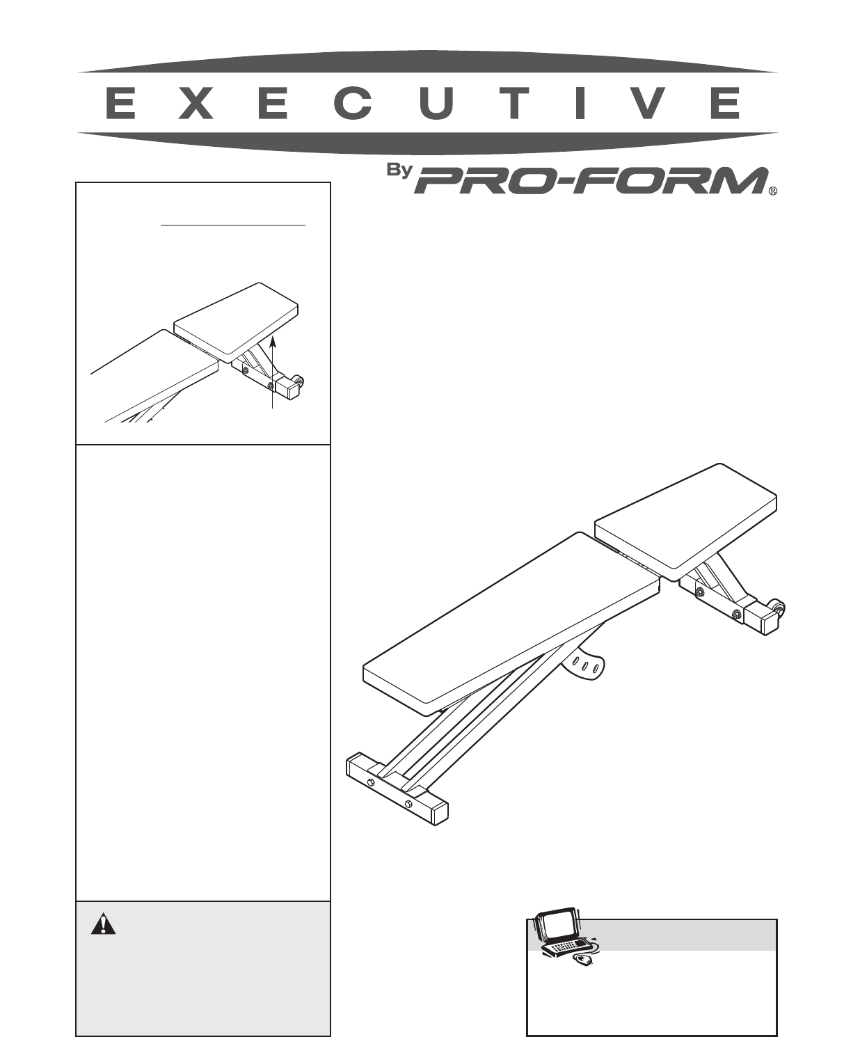
4Thank you for selecting the versatile EXECUTIVE BYPROFORM®weight bench. The weight bench isdesigned to help you develop the major muscle groupsof the
M10 Nylon Locknut (20)M6 Washer (23)M10 x 44mm Bolt (15)M10 x 231mm Hex Bolt (14)M10 x 64mm Carriage Bolt (16)M6 x 63mm Screw (19)M6 x 38mm Screw (21)
61. Before beginning, make sure that you under-stand the information in the box above. Note:Some parts described in the assembly stepsmay be pre-assem
73. Press a 50mm Thick Square Inner Cap (11) intoeach end of the Seat Frame (4).Orient the Seat (7) as shown. Attach the Seat tothe Seat Frame (4) wit
86. Refer to the inset drawing. Pull out the indicat-ed Adjustment Knob (9) as far as possible. Tipthe Seat (7) toward the Knob, and insert the SeatFr
959AdjustmentHoles8ADJUSTMENTS97ADJUSTING THE SEATTo adjust the Seat (7), pull out the front AdjustmentKnob (9) as far as possible. Move the Seat to t
Related products and manuals for Fitness, gymnastics & weight training ProForm HGBE8991.1
 (20 pages)
© 2020, manymanuals.com. All rights reserved. | 0.637 s |
 Manymanuals.com
 Manymanuals.de
 Manymanuals.fr
 Manymanuals.it
 Manymanuals.pl
 Manymanuals.cz
 Manymanuals.es
 Manymanuals-pt.com
Comments to this Manuals